First ponies, now Doctor Who. . .
Confound these fandoms, they drive people to awesome!
Anyways, I have recently finished the third season of Doctor Who, and noticed the Perception Filter Key uses an 8 pin IC.
Confound these fandoms, they drive people to awesome!
Anyways, I have recently finished the third season of Doctor Who, and noticed the Perception Filter Key uses an 8 pin IC.
555 timers have 8 pins, hmm. . .
(Read more after the break)
(Read more after the break)
It would be cool to make a device like this that would actually alter perception, but thankfully, it's currently impossible. With previous studies on infrared signals, I decided to make an IR Jammer; a device that emits infrared radiation to interfere with other devices. I saw a similar project posted by kipkay here. I tested the design on a solder-less breadboard, then designed a smaller version in SketchUp that would fit on a key. Check out some images below!
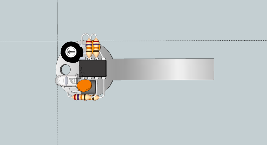
This IR Jammer uses a 555 timer to emit a constant IR beam at a specified frequency. 38khz is one of the most widely used frequency. By building the circuit accordingly with two resistors and two 10nf capacitors, it can flash an infrared light emitting diode to match that frequency, and drown out other signals. A potentiometer is used to adjust the frequency, and can support other frequencies along with 38khz. The output pin of the 555 timer was connected to the base of an NPN transistor to amplify this signal to power the IR LED, of course with a few resistors to protect these parts.
I definitely wanted to use the key itself as a conductor, and planned to solder some leads to it to secure this assembly to the key. Since there were 2 powered pins on the 555 timer as compared to only 1 ground pin, I decided to use the key itself for power (positive), and a separate wire for the ground (negative).
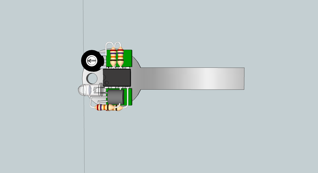
One issue with this design was that I was unable to find 10nf disk capacitors. I made a few modifications to use slightly larger mylar capacitors instead:
I definitely wanted to use the key itself as a conductor, and planned to solder some leads to it to secure this assembly to the key. Since there were 2 powered pins on the 555 timer as compared to only 1 ground pin, I decided to use the key itself for power (positive), and a separate wire for the ground (negative).
One issue with this design was that I was unable to find 10nf disk capacitors. I made a few modifications to use slightly larger mylar capacitors instead:
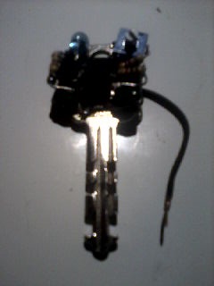
After several burns and a few other tests, I finally assembled the tiny IR jammer and soldered it to a key. I apologize in advance for the poor quality of these photos; I have yet to take pictures of the completed device with a good camera.
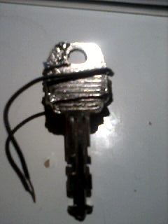 |  |
The only issues now is the limited angle of the LED and a power supply. Concerning the LED, the device needs to be directly aimed at the targeted receiver. Perhaps a wide angle LED may be a better option. With the power supply, according to the datasheets, the 555 timer requires at least 4.5 volts to operate. Two typical 3 volt coins cells would be necessary to power it, greatly increasing the size and weight of the device. I have yet to try a low power 555 timer IC and implement a battery holder. For now, I will have fun jamming IR devices with this functional replica.
 RSS Feed
